
I recently helped club member Jim Atkins replace the power brake booster in his very nice ’75 convertible. This turned out to be a more difficult job than I thought.
The power brake booster fits between the brake pedal and the brake master cylinder. It uses engine vacuum to assist the driver’s push on the brake pedal. The booster is fastened to the firewall with four studs and nuts which must be accessed way up under the instrument panel. The two lower nuts are relatively easy to access. A third one is more difficult and the fourth one is even more difficult to see or touch in a four-speed car because of the clutch pedal arm, the clutch pushrod, and especially, the clutch safety interlock switch.
Replacing the power brake booster is not an easy job, so if you attempt it, you need to know what you are doing. This is a safety-critical job, so again, you need to know what you are doing or get someone who does. A Corvette’s braking system must be properly maintained and serviced – it affects not only your safety, but the safety of everyone you meet on the road! With these important caveats in mind, here are a few hints on how to get things apart and back together with a minimum of parts removal.
You’ll want a Chevrolet shop manual for your car. The instructions and illustrations are very helpful.
Make sure you get the correct booster for your car. According to Zip Products, who sell rebuilt boosters (and lots of little bits to replace lost/missing hardware), ’68-’76 used a booster with an adjustable output pushrod that sticks out from the master cylinder mounting surface by a bit less than 1¼” (1.220 to 1.225” per the shop manual). In contrast, ’77-82 uses a booster with an output pushrod that barely sticks out from the master cylinder mounting surface. Turns out Jim’s ’75 had the ’77-82 booster installed – no wonder the brakes worked poorly.
You can get a convenient, easy-to-use gaging tool to set the booster output pushrod to match the master cylinder piston recess. Zip Products has a good video on how to use the tool to obtain the proper adjustment.
You’ll want an LED ‘headlamp’ to wear on your forehead. You’ll also want a pair of fingerless gloves to protect your knuckles from sharp edges while retaining your fingers’ sense of touch and grip on small parts in hard-to-access places.
You’ll want a long set of ratchet extensions, roughly two feet long, plus a swivel u-joint at the far end with a 9/16” deep-well socket for the booster hex nuts – we also needed an 11/16” deep well socket for the hex nuts that were installed on Jim’s faulty booster.
Obtain a 3/8” 12-point box wrench for the bolt that fastens the clutch interlock switch.
Besides the steps in the factory shop manual and YouTube videos, here are some additional hints and suggestions for the qualified service person:
Disassembly:
Remove negative battery cable from battery. Important, do not skip this!
In the engine compartment, remove master cylinder from booster. You can leave the brake lines on the master cylinder but be careful while pulling the master cylinder free of the booster. Bend the brake lines as little as possible. If you kink the lines, they are ruined, and have to be replaced.
Remove driver’s seat.
Remove steering wheel – a puller is needed for non-tilt/telescope steering columns, but not for tilt/telescope. Be sure to take some pictures as you dissemble the horn button and telescope clamp parts – they are fussy. Have a box or two on hand to save all the removed parts and fasteners.
Place a blanket on the driver’s side floor to cushion your back and climb under the dash head-first. With Jim’s convertible, I was able to stick my legs up on the folded convertible top. Don’t forget the ‘headlight’ and position tools next to you for easier access.
Remove T-shaped trim panel that covers the bottom of steering column. Separate the headlight vacuum bypass ‘switch’ from the panel carefully.
Remove AC duct under the steering column. It’s fastened with just one screw. Remove that and you can wiggle the duct out.
To get at the upper right booster nut, carefully remove the 3/8” hex bolt that fastens the interlock switch to the pedal bracket. I planned to let the interlock switch dangle there by the linkage, but the linkage fell apart at the top where the link goes into the pedal arm. I think the last tech who did this job left out a bushing and retaining clip way up high where you can’t even see it.
Now all four hex nuts for the booster can be accessed. Loosen them a little. Then remove the spring clip that retains the brake pedal clevis pin, and then remove the pin from the brake clevis.
Fully remove the four hex nuts from the booster and wiggle the booster out from the engine compartment.
Reassembly:
Double and triple check the output pushrod adjustment per the Zip Products video. Use a small dot of LocTite® per the video to assure adjustment is secured.
Install the original clevis to the input pushrod. Rotate the clevis so it’ll be vertical when you reinsert the booster into the firewall mounting holes. A small dot of blue LocTite® on the threads helps assure the clevis does not work loose.
Feed the booster back in through the firewall and make sure the clevis enters the brake pedal lever properly. Start the four hex nuts on the booster studs, snug them, then reinstall the clevis pin and clip. Then retighten the hex nuts to securely fasten the booster to the firewall.
Reinstall the master cylinder. Connect the booster vacuum hose to the booster. Be sure the vacuum check valve is in place on the booster
Make an initial test. With the engine off, the brake pedal must have normal travel, with brakes applied well before the pedal gets anywhere near the floor, and the pedal must feel very firm. If that passes, you can, reconnect the battery, temporarily jumper the clutch interlock switch, and making sure the car is in neutral and with the clutch pushed in, start the car to make sure the vacuum assist functions properly, with no hissing sound with pedal pushed in and with a higher brake pedal now that vacuum is supplied by the engine.
If the brakes are performing properly in the initial test, you can continue the reassembly. Again, be sure to disconnect the negative lead from the battery.
Zip Products supplied the missing bushing and retaining clips for the clutch interlock switch.
To access the top of the interlock link, install bushing and retaining clip, I had to first remove the clutch pushrod, both at the clutch pedal under the dash (not easy) and at the cross shaft in the engine compartment. With the pushrod out of the way I could install the link, nylon bushings (two) and top retaining clip (not easy).
Reinstall the interlock switch properly and insert the lower end of the link and retaining clip. Then reinstall the clutch pushrod (with a little grease on the pivots) and the retaining clips for each end of the clutch pushrod.
Carefully reassemble the telescope steering lock, steering wheel, and horn switch, and driver’s seat, reconnect the battery, test the horn. Reinstall the AC duct, and column lower trim panel.
Again all of this work is safety critical so do it carefully and correctly, or have someone who can do it properly and carefully.
Take a very careful test ride removed from all traffic to make sure everything works correctly. If it does not work properly, get things corrected. For safety’s sake, do not operate a car with imperfect brakes.
With the transmission in neutral, make sure the clutch interlock switch lets the starter crank with the clutch pedal pushed down, but does not allow the starter to crank when the clutch pedal is up.
Take some careful, slow test rides close to your home or workshop to make sure your brake system is functioning properly. If all performs properly, enjoy your Corvette again! If not, take corrective actions. No short cuts.
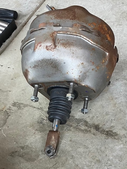
The power brake booster removed from Jim’s car.
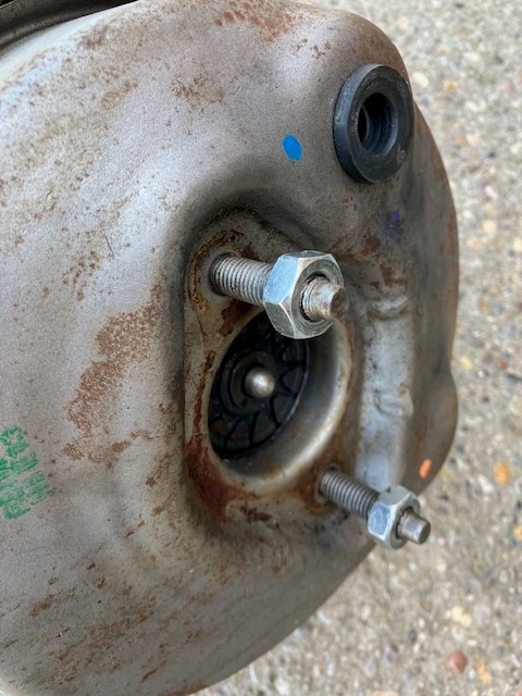
Power brake booster, output rod end is too short for Jim’s ’75 Corvette.
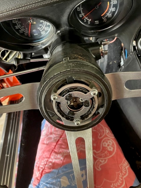
View of the end of the steering column with the horn button removed.
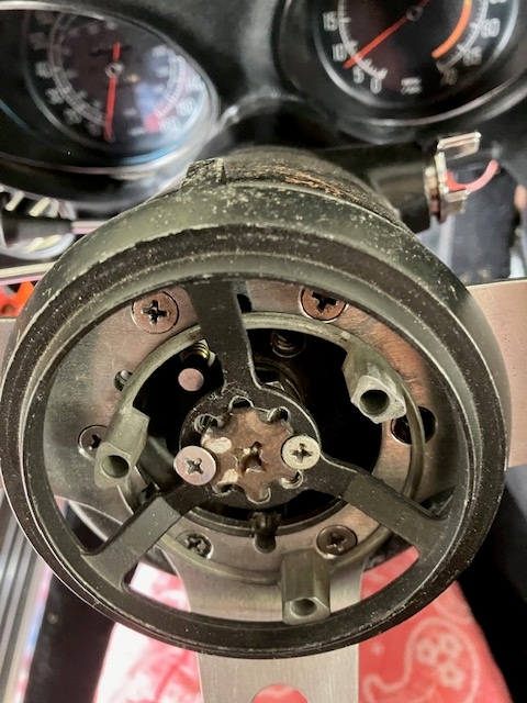
With horn switch and steering wheel removed, telescope lock is visible.
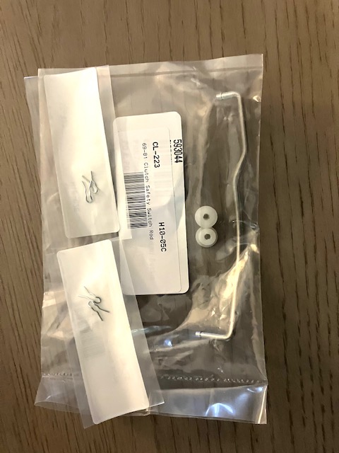
Replacement clutch interlock switch linkage, bushings for upper end, and retaining clips for upper and lower ends.
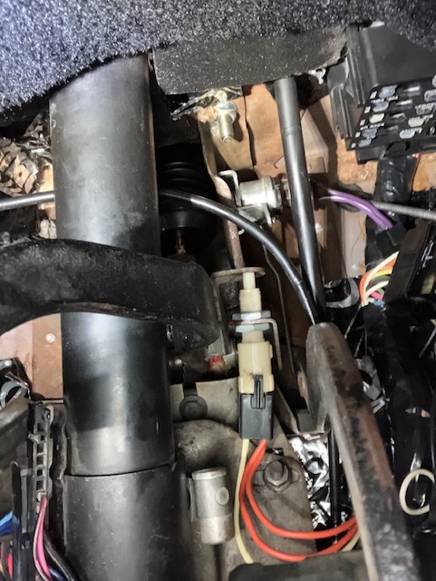
View looking up under the dash. One of the lower booster retaining nuts visible at center, clutch pushrod (black), and clutch interlock switch (silver).
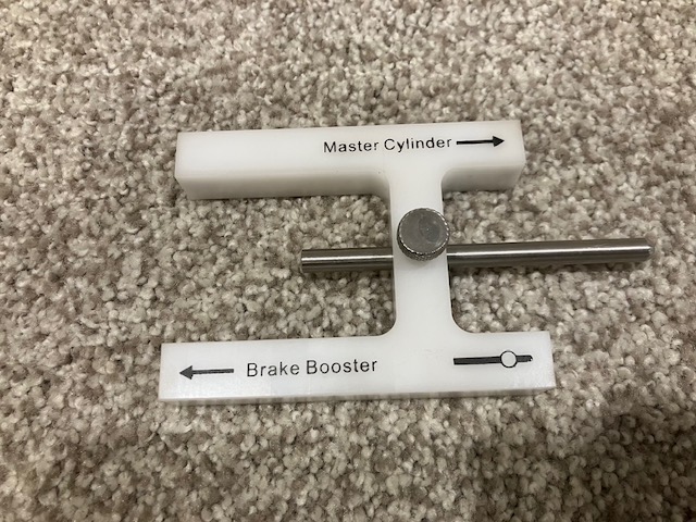
Tool for setting the booster output rod to same depth as socket in end of master cylinder piston.